Aux Analog Input Setup
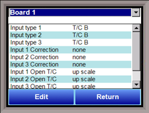
The Auxiliary Analog Input Setup menu option allows the user an input selection of three inputs per board, three input corrections per board, and three input open T/Cs per board. There are eight (8) boards available. It is configurable for voltage of T/C (universal input), and it is typically used for Load T/Cs, motor speed feedback, current speed devices, and Auxiliary Flow Meters.
Before connecting your input source to the terminals, please verify that the input type is set up correctly. If the Input Type is not correct, do not connect the input source to the terminals, as damage can occur. Please consult SSi by calling (513) 772-0060 before making any changes.
Input 1 – Input 3
This will select the input types for the board. The options are:
T/C B
T/C C
T/C E
T/C J
T/C K
T/C N
T/C NNM
T/C R
T/C S
T/C T
2.5 volts
1.25 volts
80 mV
40 mV
20 mV
4-20 mA/124Ω
4-20 mA/62 Ω
25 volts
12.5 volts
Input 1 Correction – Input 3 Correction
This option will set a correction curve for the input. The options for the input corrections are: not used, Curve 1 – Curve 3.
Input 1 Open T/C – Input 3 Open T/C
This option will allow the user to set the direction of the open T/C for each input. The options are: Up Scale or Down Scale.
Calibration (Auxiliary Analog Inputs)
The user will need a calibrator capable of outputting a temperature, voltage, and millivolt signal to calibrate the zero, span or cold junction value. The user will need to connect the calibrator to one of the inputs on the data logger for the channel that will be calibrated. It is recommended to let everything (calibrator and data logger) sit for approximately thirty minutes to allow the temperature to achieve equilibrium. Set up the calibrator for the specific thermocouple type, i.e. type K, type J, etc. Then, source a specific temperature, like 1000°F, or millivolt to the connected input. It is recommended that the actual temperature used be similar to an appropriate process temperature. For example, if your equipment normally operates at 1700°F, then perform the cold junction calibration using a 1700 °F signal. It is important to note that when performing a zero or span calibration, do not use regular thermocouple wiring. Instead, use any kind of regular sensor wire, or even regular copper wire. To perform the calibrations, the user will need a calibrator that is capable of outputting volts, millivolts, and temperature.
The “Zero/Span” tab will allow the user to perform a zero and span calibration on the selected board.
The help button -  - next to the “Range” drop-down list will allow the user to select a range based upon an input type if the range is not known.
Select the input type and click on the OK button. The correct millivolt range will be displayed in the drop-down list. Click on the Cancel button to cancel this action.
Below is a listing of the suggested ranges for the various TC types.
| TC Type | Range in mV |
|---|---|
| B | 17.5 |
| C | 65 |
| E | 65 |
| J | 65 |
| K | 65 |
| N | 65 |
| NNM | 65 |
| R | 65 |
| S | 17.5 |
| T | 65 |