Calibration
Before using the SDS Data Logger in surveys, it is essential to ensure that the unit is properly calibrated. This means that raw voltages measured by instruments connected to the data logger are converted (scaled) to values that accurately reflect the actual voltages. The calibrations that the user will typically need to perform (before using the data logger in surveys) are the Voltage Calibration and Cold Junction Trim Calibration (also called CJ Trim). First, the Voltage Calibration will be performed to ensure that the voltages measured by the leads connected to each thermocouple are scaled correctly. Second, the CJ Trim will be performed to ensure that the temperature measured at each data logger terminal (where the cold junction is created) is correctly scaled. Both types of calibration require a sourcing device and thermocouple wire. The sourcing device should be calibrated and certified to generate accurate voltages before these calibrations are performed.
|
IMPORTANT: Do not perform any of these calibrations without a sourcing device that is properly connected and sourcing voltage into the proper inputs on the Color SDS Data Logger. Running a calibration without a sourcing device that is providing voltage into the unit may require additional calibration steps. |
Voltage Calibration
The leads that connect to each input thermocouple measure the voltage generated by that thermocouple. In most cases, the voltage that the data logger detects (the raw voltage) is slightly different from the actual voltage generated by the thermocouple. When properly performed, a Voltage Calibration (also called an Input Calibration) ensures that the SDS Data Logger software properly scales the raw voltage so that an accurate temperature can be calculated. The Voltage Calibration consists of two parts: a Zero Calibration and a Span Calibration. A Zero Calibration ensures that the raw voltage is scaled properly when the actual voltage at a thermocouple is zero volts. A Span Calibration ensures that the raw voltage is scaled properly when the actual voltage is 90% of the upper limit of the desired range (for example, 72 mV when the upper limit of the range is 80 mV).
Figure 39 - Voltage Calibration screen shows what the Voltage Calibration screen looks like.
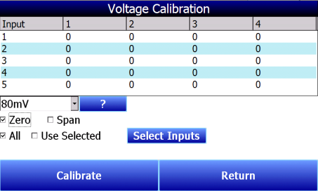
Figure 39 - Voltage Calibration screen
The horizontal row of numbers represents each circuit board containing five inputs. The vertical column of numbers represents each individual input. A 20-input SDS Data Logger will feature four circuit boards depicted on this screen, while a 40-input unit will feature eight circuit boards. Since each board has five inputs, a Voltage Calibration usually involves five inputs on the same board at one time. A single input can be calibrated if it is suspected that the temperature reading associated with one input is incorrect.
Range Value: The mV value shown in the drop-down box represents the range value for the particular kind of thermocouple wire that you are using in the calibration. Pressing the question mark (“?”) will bring up a window that shows the range value specific to various kinds of thermocouple wire.
Zero or Span: Check “Zero” to perform a Zero Calibration. Check “Span” to perform a Span Calibration.
All or Use Selected: Check “All” to calibrate all inputs. Check “Use Selected” to calibrate a group of inputs selected by pressing the Select Inputs button and choosing the inputs that you want to calibrate.
Set up your calibration device as needed. When ready to begin calibrating, press Calibrate.
|
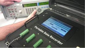
Figure 40 - Setting Up A Voltage Calibration |
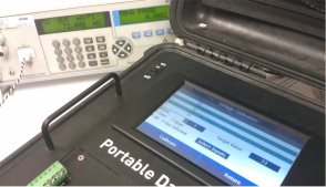
Figure 41 - Voltage Calibration (Span) |
Use the results of the calibration to set up offsets for the SDS Data Logger. Editing offsets is described in the “Edit Offsets” section above.
CJ Trim
For the Trim calibration, TC wire should be used. The trim calibration is performed by connecting a thermocouple calibration device to each input and outputting a trim temperature that should be equal to the expected operating temperature. For example, the calibration could be completed using an output temperature of 1700°F. After the zero calibration and span calibration, the temperature may read 1701.5°F instead. This type of calibration should be used instead of the regular cold junction thermistor calibration unless the cold junction temperatures are reading a temperature that is much too high for what the ambient temperature could possibly be. A cold junction thermistor calibration can be used in this instance when need be, but the Trim Calibration is preferred.
IMPORTANT: Before performing this calibration:
-
Ensure that a sourcing device is properly connected and sourcing voltage into the proper inputs on the Color SDS Data Logger.
-
Ensure that the input types are set up correctly. See View Input Types and, if necessary, Edit Input Types.
-
If the data logger has been brought inside from a cold environment, wait 30 minutes before performing the Cold Junction Trim Calibration. This will provide enough time for the data logger to reach a stable temperature.
To perform a cold junction trim, first select the thermocouple type from the dropdown list. Select the inputs that will be included by pressing the Select Inputs button. Enter the Target Value and press Calibrate.
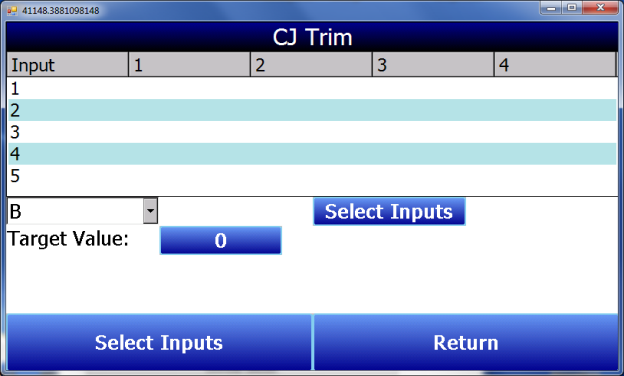
Figure 42 - CJ Trim Screen
Cold Junction Thermistor Calibration
This procedure is performed by Super Systems Inc. before the SDS Data Logger is shipped. In most cases, the procedure will not need to be performed in the field. If a situation should arise where a cold junction calibration may need to be performed in the field, please contact Super Systems Inc. Technical Support at 513-772-0060.